
History[]
Lua error in package.lua at line 80: module ‘Module:Message box/configuration’ not found.
Throughout the 1950s and 1960s, various federal, state and local governments in the United States conducted studies into the numerous sources of air pollution. These studies ultimately attributed a significant portion of air pollution to the automobile, and concluded air pollution is not bounded by local political boundaries. At that time, such minimal emission control regulations as existed in the U.S. were promulgated at the municipal or, occasionally, the state level. The ineffective local regulations were gradually supplanted by more comprehensive state and federal regulations. By 1967 the State of California created the California Air Resources Board, and in 1970, the federal United States Environmental Protection Agency (EPA) was established. Both agencies, as well as other state agencies, now create and enforce emission regulations for automobiles in the United States. Similar agencies and regulations were contemporaneously developed and implemented in Canada, Western Europe, Australia, and Japan.
The first effort at controlling pollution from automobiles was the PCV (positive crankcase ventilation) system. This draws crankcase fumes heavy in unburned hydrocarbons — a precursor to photochemical smog — into the engine’s intake tract so they are burned rather than released unburned from the crankcase into the atmosphere. Positive crankcase ventilation was first installed on a widespread basis by law on all new 1961-model cars first sold in California. The following year, New York required it. By 1964, most new cars sold in the U.S. were so equipped, and PCV quickly became standard equipment on all vehicles worldwide.
The first legislated exhaust (tailpipe) emission standards were promulgated by the State of California for 1966 model year for cars sold in that state, followed by the United States as a whole in model year 1968. The standards were progressively tightened year by year, as mandated by the EPA.
By the 1974 model year, the emission standards had tightened such that the de-tuning techniques used to meet them were seriously reducing engine efficiency and thus increasing fuel usage. The new emission standards for 1975 model year, as well as the increase in fuel usage, forced the invention of the catalytic converter for after-treatment of the exhaust gas. This was not possible with existing leaded gasoline, because the lead residue contaminated the platinum catalyst. In 1972, General Motors proposed to the American Petroleum Institute the elimination of leaded fuels for 1975 and later model year cars. The production and distribution of unleaded fuel was a major challenge, but it was completed successfully in time for the 1975 model year cars. All modern cars are now equipped with catalytic converters and leaded fuel is nearly impossible to buy in most First World countries.
History
Throughout the 1950s and 1960s, various federal, state and local governments in the United States conducted studies into the numerous sources of air pollution. These studies ultimately attributed a significant portion of air pollution to the automobile, and concluded air pollution is not bounded by local political boundaries. At that time, such minimal emission control regulations as existed in the U.S. were promulgated at the municipal or, occasionally, the state level. The ineffective local regulations were gradually supplanted by more comprehensive state and federal regulations. By 1967 the State of California created the California Air Resources Board, and in 1970, the federal United States Environmental Protection Agency (EPA) was established. Both agencies, as well as other state agencies, now create and enforce emission regulations for automobiles in the United States. Similar agencies and regulations were contemporaneously developed and implemented in Canada, Western Europe, Australia, and Japan.
The first effort at controlling pollution from automobiles was the PCV (positive crankcase ventilation) system. This draws crankcase fumes heavy in unburned hydrocarbons – a precursor to photochemical smog – into the engine’s intake tract so they are burned rather than released unburned from the crankcase into the atmosphere. Positive crankcase ventilation was first installed on a widespread basis by law on all new 1961-model cars first sold in California. The following year, New York required it. By 1964, most new cars sold in the U.S. were so equipped, and PCV quickly became standard equipment on all vehicles worldwide.
The first legislated exhaust (tailpipe) emission standards were promulgated by the State of California for 1966 model year for cars sold in that state, followed by the United States as a whole in model year 1968. Also in 1966, the first emission test cycle was enacted in the State of California measuring tailpipe emissions in PPM (parts per million). The standards were progressively tightened year by year, as mandated by the EPA.
By the 1974 model year, the United States emission standards had tightened such that the de-tuning techniques used to meet them were seriously reducing engine efficiency and thus increasing fuel usage. The new emission standards for 1975 model year, as well as the increase in fuel usage, forced the invention of the catalytic converter for after-treatment of the exhaust gas. This was not possible with existing leaded gasoline, because the lead residue contaminated the platinum catalyst. In 1972, General Motors proposed to the American Petroleum Institute the elimination of leaded fuels for 1975 and later model year cars. citation needed The production and distribution of unleaded fuel was a major challenge, but it was completed successfully in time for the 1975 model year cars. All modern cars are now equipped with catalytic converters, and leaded fuel is no longer sold at filling stations in most First World countries. Leaded racing fuel is available in small quantities from some suppliers, but it is legal for off-road use only.
Applications of Emission Control Systems
- Emission control systems can transform these pollutants into water vapor and carbon dioxide, which may then be safely discharged or recirculated into the environment.
- These systems are used in the automotive, pharmaceutical, medical, microelectronic, bio-safe laboratories, and aerospace sectors, to name a few.
- These control systems are found in power plants and metallurgical facilities.
- A pollution control system is used in oil and gas refineries.
- Air pollution control systems are used in chemical manufacturing because of the gases and contaminants in the environment.
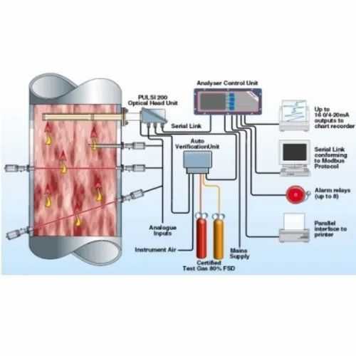
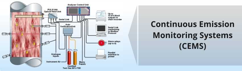
- Many facilities use continuous emissions monitoring systems to help manage and monitor dangerous discharges, making reporting to federal and state supervisory bodies easier.
Emissions control[]
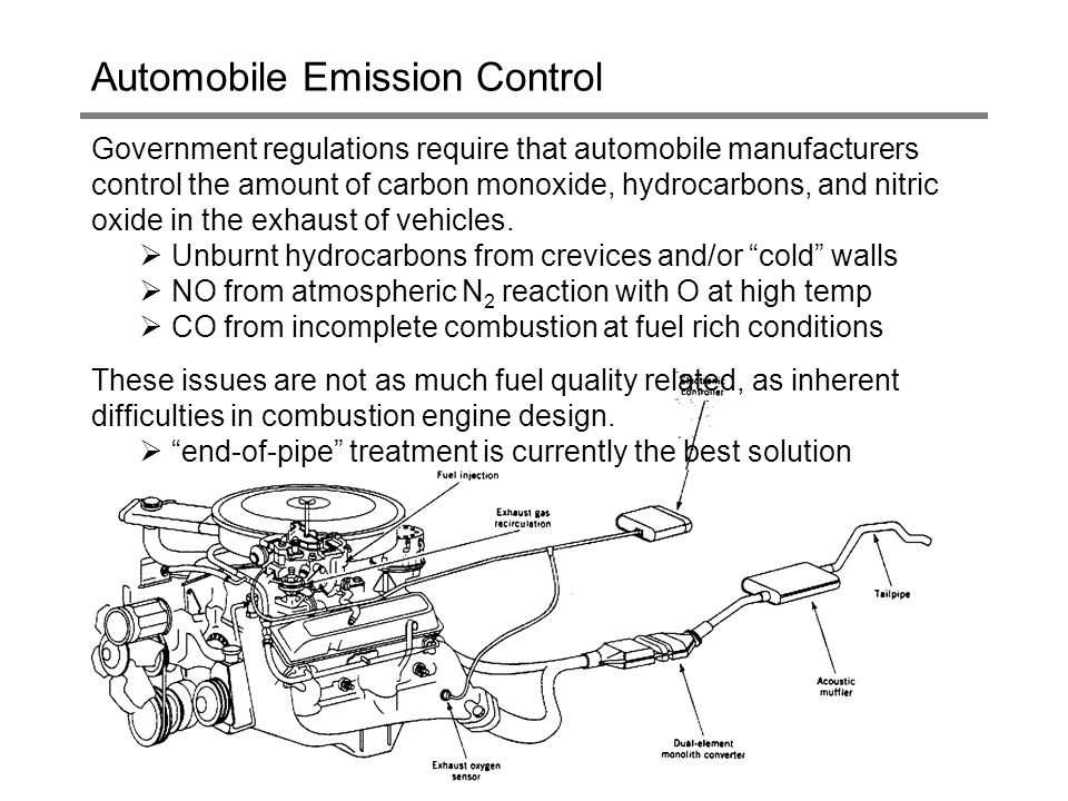
Engine efficiency has been steadily improved with improved engine design, more precise ignition timing and electronic ignition, more precise fuel metering, and computerized engine management.
Advances in engine and vehicle technology continually reduce the toxicity of exhaust leaving the engine, but these alone have generally been proved insufficient to meet emissions goals. Therefore, technologies to detoxify the exhaust are an essential part of emissions control.
Air injection
- Main article: Secondary air injection
One of the first-developed exhaust emission control systems is secondary air injection. Originally, this system was used to inject air into the engine’s exhaust ports to provide oxygen so unburned and partially burned hydrocarbons in the exhaust would finish burning. Air injection is now used to support the catalytic converter’s oxidation reaction, and to reduce emissions when an engine is started from cold.
After a cold start, an engine needs an air-fuel mixture richer than what it needs at operating temperature, and the catalytic converter does not function efficiently until it has reached its own operating temperature. The air injected upstream of the converter supports combustion in the exhaust headpipe, which speeds catalyst warmup and reduces the amount of unburned hydrocarbon emitted from the tailpipe.
Exhaust gas recirculation
- Main article: Exhaust gas recirculation
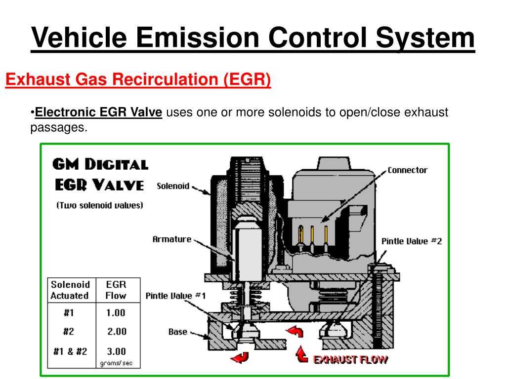
In the United States and Canada, many engines in 1973 and newer vehicles (1972 and newer in California) have a system that routes a metered amount of exhaust into the intake tract under particular operating conditions. Exhaust neither burns nor supports combustion, so it dilutes the air/fuel charge to reduce peak combustion chamber temperatures. This, in turn, reduces the formation of NOx.
Catalytic converter
- Main article: Catalytic converter
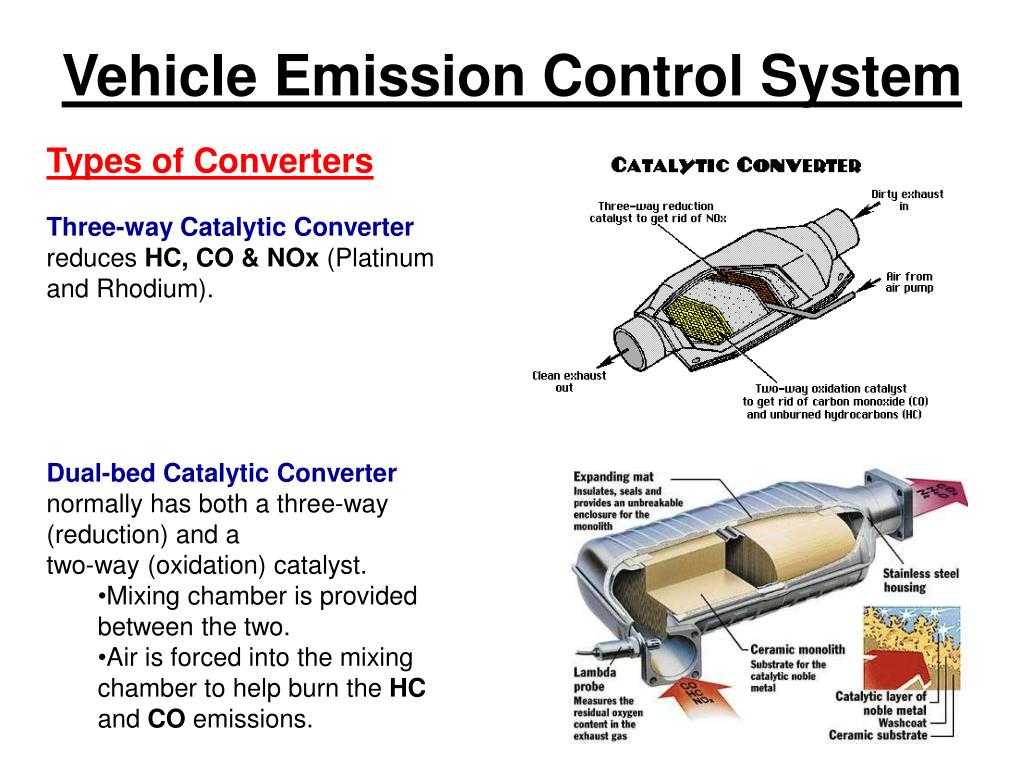
The catalytic converter is a device placed in the exhaust pipe, which converts hydrocarbons, carbon monoxide, and NOx into less harmful gases by using a combination of Pt, Pd and Rh as catalysts.
There are two types of catalytic converter, a two-way and a three-way converter. Two-way converters were common until the 1980s, when three-way converters replaced them on most automobile engines. See the catalytic converter article for further details.
Families Citing this family (12)
| Publication number | Priority date | Publication date | Assignee | Title |
|---|---|---|---|---|
|
EP2059329B1 * |
2006-09-05 | 2015-06-03 | Clue As | Flue gas desulfurization process |
|
AU2007295937A1 * |
2006-09-11 | 2008-03-20 | Woodside Energy Limited | Boil off gas management during ship-to-ship transfer of LNG |
|
WO2013093536A1 * |
2011-12-20 | 2013-06-27 | Moanda Antoine Marie-Romain | Toxic gas absorber/isolator and instantaneous neutralization process |
|
SE538470C2 * |
2014-02-21 | 2016-07-12 | Celective Source Ab | Procedure for establishing a temporary connection |
|
ITUB20151849A1 |
2015-07-02 | 2017-01-02 | Green Eng S R L | NAVAL EMISSION TREATMENT PLANT IN THE DOORS |
|
US10422260B2 * |
2015-08-06 | 2019-09-24 | Clean Air-Engineering-Maritime, Inc. | Movable emission control system for auxiliary diesel engines |
|
CN105109656A * |
2015-08-31 | 2015-12-02 | 广新海事重工股份有限公司 | Rotatable chimney for ship |
|
TWI762502B * |
2016-08-08 | 2022-05-01 | 美商淨化空氣工程海事股份有限公司 | Emissions reduction systems and emissions reduction methods |
|
WO2019226348A1 * |
2018-05-25 | 2019-11-28 | Clean Air-Engineering — Maritime, Inc. | Movable emission control system for auxiliary diesel engines |
|
IT201900008235A1 * |
2019-06-06 | 2020-12-06 | Enrico Festa | DEVICE TO CAPTURE NAVAL EMISSIONS IN PORTS |
|
US11480089B1 |
2021-06-29 | 2022-10-25 | Greener Process Systems Inc. | In-port ship exhaust capture device |
|
US11634203B2 * |
2021-06-29 | 2023-04-25 | Greener Process Systems Inc. | In-port ship exhaust capture device |
OTHER EMISSION CONTROL PARTS
On older engines with a carburetor, one of several emission control devices may be used to reduce emissions during warm-up. Fuel vaporizes slowly when it is cold, so heating the air before it enters the carburetor or throttle body improved fuel vaporization and allows the engine to more easily maintain a balanced air/fuel mixture. Most such engines have a heated air intake system that draws warm air from a stove around the exhaust manifold into the air cleaner.
A thermostat inside the air cleaner controls vacuum to a valve in the air cleaner inlet. When the engine is cold, the thermostat passes vacuum to the control valve, which closes a flap to outside air allowing heated air to be drawn into the air cleaner. As the engine warms up, the thermostat begins to bleed air, allowing the control door to open to outside air. Thus the thermostat and airflow control door are able to maintain a more consistent incoming air temperature.
One part that is often needed here is the flexible tubing that connects the air cleaner to the exhaust stove. If damaged or missing, the engine may hesitate and stumble when cold.
Another early fuel evaporation aid on older V6 and V8 engines is a heat riser valve. The valve is located on one exhaust manifold. When the engine is cold, the valve closes to blocks the flow of exhaust so it will be forced back through a crossover passage in the intake manifold directly under the carburetor. The hot exhaust heats the manifold to speed fuel vaporization and engine warm-up. Once the engine warms up, the heat riser valve opens. The heat riser valve needs to be replaced if it is sticking or inoperative.
On some older engines, an electrically-heated EFE grid is used under the carburetor or throttle body to aid fuel vaporization when the engine is cold. A timer turns the grid off after a fixed period of time. If the grid fails to heat (bad relay, electrical connection, etc.), the engine may hesitate and stumble when cold. Electric heater grids in the intake system are also used on some late model diesel engines for easier starting and cold performance.


In the early 1980s, domestic auto makers replaced mechanical carburetors with Electronic carburetors to reduce pollution and improve performance and fuel economy. Electronic carburetors used a computer-controlled solenoid to vary the Air/Fuel ratio using inputs to the engine computer from an oxygen sensor in the exhaust. Electronic carburetors proved to be quite troublesome, and were eventually phased out and replaced with Fuel Injection, including both Throttle Body Injection systems (TBI) and Multi-Port Fuel Injection (MFI) systems.
Electronic Fuel Injection (EFI) proved to be much better at reducing emissions while also greatly improving cold start idle quality, overall engine performance and fuel economy. EFI eliminated the troublesome choke mechanism that was used on carburetors for cold starting and fast idle during engine warm-up. EFI also sprayed fuel directly into the intake manifold or intake ports, which improved fuel atomization for better air/fuel mixing and cleaner combustion. Multi-port fuel injection also allowed more even cylinder-to-cylinder fuel distribution which improved horsepower and fuel economy. what’s more, throttle response with EFI was much crisper with no throttle lag or bogging (both of which were common problems with carburetors).
 Small fuel vapor leaks in the EVAP system plumbing can set a P0442 code and turn on the Check Engine light.
Common Components of EEC System
The fuel tank filler caps used on cars with EEC systems differ from those used on cars without EEC systems. Most caps in EEC system are incorporated with built in pressure-vacuum relief (Fig. 17.20), so that a vacuum lock may develop due to the fuel expansion or contraction. Fuel tanks are protected in different ways against fuel expansion and overflow, caused by heat. An overfill limiter, or temperature expansion tank, was fitted on many 1970-73 EEC systems to limit total filling of the tank. This is installed inside the fuel tank and has small holes, which open it to the fuel area. When the fuel tank appears to be completely full, it holds no more and the fuel gauge reads full although the expansion tank remains virtually empty. This offers enough space for the expansion of fuel and
collection of vapour if the vehicle is parked in the hot sun after filling the tank.Fig. 17.18. PCV valve operation in case of backfire.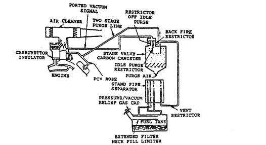 Fig. 17.19. Evaporative emission control system
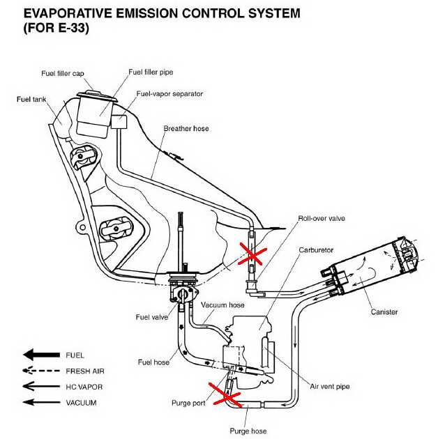
The dome shape of the upper portion of the fuel tank incorporated in some later-model cars, or the overfill limiting valve installed inside the vapour-liquid separator, eliminates the need for the overfill limiter tank fitted in earlier systems.
Some Ford-built cars use a combination valve, which performs the following tasks :
(i) It isolates the fuel tank from engine pressures and permits vapour to escape from the vapour separator tank to the vapour storage canister.Fig 17.20. EEC systems fuel tank caps.
(ii) It vents excess fuel tank pressure to the atmosphere in case the vapour delivery line is blocked.
(Hi) It allows fresh air to be drawn into the fuel tank to fill the space created by petrol as it is used.
All EEC systems incorporate some type of liquid-vapour separator to prevent liquid fuel from reaching the engine crankcase or vapour storage canister. Some liquid-vapour separators are contained within the tank and use a single vapour vent line from the tank to the vapour canister. When the separator is not built into the tank (Fig. 17.21) it is usually installed on the outside of the tank or on the frame near it. In this case, vent lines extend from the tank to the separator and are arranged to vent the tank, irrespective of whether the car is on a level surface or not. Liquid fuel entering the separator returns to the tank through the shortest line.17.21. Liquid-vapour separator is mounted separately from the tank.
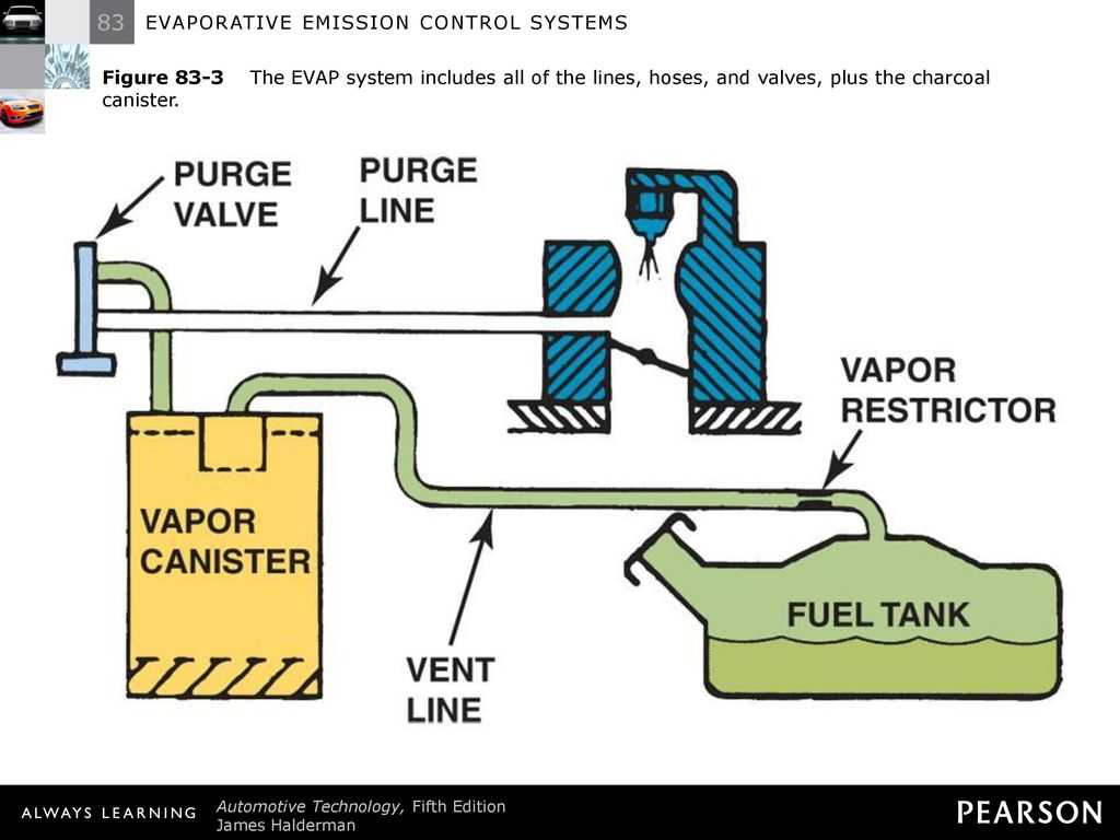
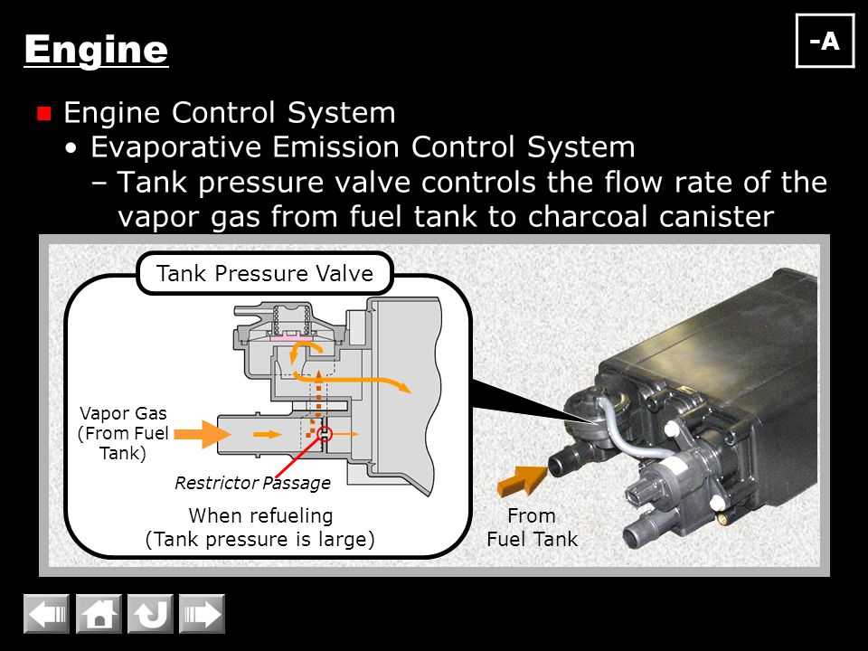
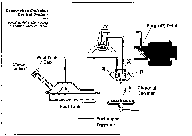
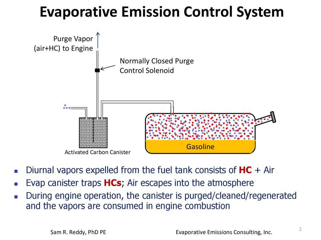
EVAP system
Evaporative emissions from the fuel system (fuel vapors) are trapped and store in a charcoal canister. Later, a purge valve opens allowing the vapors to be sucked into the engine and reburned. The EVAP system usually requires no maintenance. The fuel filler cap is also part of the EVAP system, and is designed to keep fuel vapors from escaping into the atmosphere. A leaky or missing fuel filler cap may cause a vehicle to fail an emissions test.
OBD II
Starting as early as 1994, some U.S. vehicles were equipped with a new government mandated Onboard Diagnostic (OBD II) system. By model year, 1996, OBD II was required on all new cars and light trucks.
OBD II is designed to detect emission problems. When a problem is detected, the Check Engine light comes on and a diagnostic trouble code is stored in the powertrain computer (PCM). Later, the code can be read using a scan tool to determine the nature of the problem.
With OBD II, the Check Engine light will come on anytime emissions exceed federal limits by 50% on two consecutive trips, or there is a failure of a major emissions control system. With earlier engine control systems, the only way to uncover most emission problems is to give the vehicle an emissions test, which is not required in many rural areas. But OBD II is on every 1996 and newer car and light truck regardless of where it is registered in the U.S. And unlike an emissions test which may only be given once every year or two, OBD II is monitoring emissions performance every time the vehicle is driven. Many areas now check emissions by performing an OBD II plug-in emissions test. The test checks to see that all the OBD II system monitors have run, that the Malfunction Indicator Lamp (MIL) is working (an OFF), and there are NO stored diagnostic trouble codes (DTCs) in the PCM’s memory. Most states that do emissions testing now do a quick OBD II plug-in check rather than tailpipe testing to verify emissions compliance.
More Emissions Articles:
Understanding OBD II Driveability & Emissions ProblemsOBD II Plug-In Emissions TestingFixing Emission FailuresAll About Onboard Diagnostics II (OBD II)Exhaust Emissions DiagnosisTroubleshooting a P0420 Catalyst CodeCatalytic ConvertersExhaust Gas Recirculation (EGR)Positive Crankcase Ventilation (PCV)EVAP Evaporative Emission Control SystemFinding & Fixing Vacuum LeaksUnderstanding Oxygen (O2) SensorsWide Ratio Air Fuel (WRAF) SensorsSensing Emission Problems (O2 Sensors)Emission Control Basics Self-Test QuizOBD2 Basics Self-Test Quiz Click Here to See More Carley Automotive Technical ArticlesBe sure to visit our other websites: AA1Car Automotive Diagnostic & Repair Help Auto Repair YourselfCarley Automotive SoftwareOBD2HELPRandom-MisfireScanToolHelpTROUBLE-CODES
Retrofit emission control application & service in India – Choose the right retrofit emission control solution
To perceive the first-rate product which suits your need, make a go to our sales & production unit. With years of enjoyment we are the legal manufacturer & carrier company of retrofit emission discount gadgets in India. All our merchandise comply with the economic general norms to make your commercial generator greater efficient & reliable. A few most important useful functions of our carrier.
- Product production is primarily based totally at the desires of the application.
- Low shopping for the fee of the retrofit emission manipulation device.
- Testing in all parameters earlier than installation.
- Availability for each new or lifestyles Genset.
- High-grade materials & remarkable relative technology.
Internal Combustion engines generate unwanted emissions all through the combustion process. The main reasons of those emissions are non-stoichiometric combustion, dissociation of nitrogen and impurities withinside the gasoline and air. Emission control system managed structures are mounted in automobiles for the motive of decreasing the release of those noxious gases. These structures consciousness on minimizing crankcase, evaporative, and tailpipe exhaust emissions. There are 3 simple methods wherein automobiles make a contribution to pollution.
- Crankcase emissions.
The combustion reactions taking location produce sure via way of means of merchandise and unburned gasoline gift constitutes the crankcase emissions. In order to recirculate those gases lower back into the car’s engine, a PCV (high-quality crankcase ventilation) device is used. An EGR valve is likewise furnished and its primary feature is to recirculate a few parts of the exhaust fuel line and run it via the combustion method again. The end result of that is an extra entire combustion.
- Evaporative emissions.
The evaporative emissions resulting from the vaporization of gas comes from sources, one is the carburetor and the other is the gasoline tank. The ELCD (Evaporation Loss Control Device) controls evaporative emissions with the aid of shooting the vapors and recirculating them. This tool includes an absorbent chamber, a stress stability valve and a purge-managed valve. Emissions are restrained with the aid of sealing the vehicle’s gasoline gadget and preserving the vapors in a canister for reburning.
- Tailpipe exhaust emissions
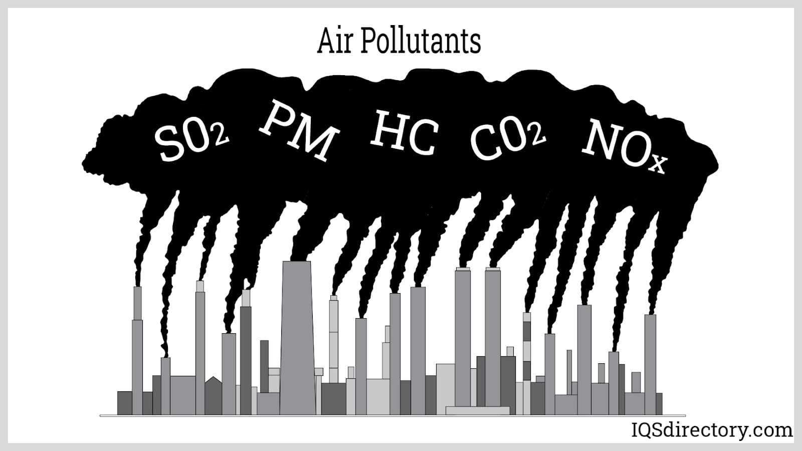
Unburned hydrocarbons, carbon monoxide, and nitrogen oxides represent the majority of tailpipe emissions. Several emissions management structures limit the introduction of those pollutants, consisting of the catalytic converter and unique gas calibration.
emission control system
emission-control system — automotive technology in automotive engineering, means employed to limit the discharge of noxious gases from the internal combustion engine. There are four main sources of these gases: the engine exhaust, the crankcase, the fuel tank, and … Universalium
evaporative emission control system — (EVAP pr EEC) A system for reducing evaporative emissions by means of a sealed fuel tank, a vapour liquid separator, a three way valve, an activated carbon filter, and a network of interconnecting hoses. Also called evaporation control system … Dictionary of automotive terms
exhaust emission control system — A general term for any system that reduces the harmful exhaust emissions of a motor vehicle, including one or all of the following systems: catalytic converter (with or without oxygen sensor air/fuel control), exhaust gas recirculation, secondary … Dictionary of automotive terms
crankcase emission control system — noun Engine subsystem … Wiktionary
emission control — A system for restricting the amount of noxious emissions. There are two standards for emission controls: level E for Europe and the more stringent level U for the United States. See exhaust emission control evaporative emission control system … Dictionary of automotive terms
evaporative emission shed system — (EESS) a Ford evaporative emission control system introduced in 1978 … Dictionary of automotive terms
thermactor exhaust control system — (TEC) an air injector type of exhaust emission control system used by Ford … Dictionary of automotive terms
control — A device or mechanism for adjusting a component. See cruise control. The ability of the driver to make a vehicle perform as required. To regulate. Automatic or manual device used to stop, start, and/or regulate flow of gas, liquid … Dictionary of automotive terms


-
Monitor driver is successfully installed что это
-
Как в скайриме убить порождение пепла
-
Hill climb racing 2 как перенести достижения на другой телефон
-
Fifa 21 карточки а что если
- Даже когда верблюд дезире хочет пить 84 его веса составляет вода
Regulatory agencies[]
The agencies charged with regulating exhaust emissions vary from jurisdiction to jurisdiction, even in the same country. For example, in the United States, overall responsibility belongs to the EPA, but due to special requirements of the State of California, emissions in California are regulated by the Air Resources Board. In Texas, the Texas Railroad Commission is responsible for regulating emissions from LPG-fueled rich burn engines (but not gasoline-fueled rich burn engines).
North America
- California Air Resources Board — California, United States (most sources)
- Environment Canada — Canada (most sources)
- Environmental Protection Agency — United States (most sources)
- Texas Railroad Commission — Texas, United States (LPG-fueled engines only)
- Transport Canada — Canada (trains and ships)
Europe
The European Union has control over regulation of emissions in EU member states; however, many member states have their own government bodies to enforce and implement these regulations in their respective countries. In short, the EU forms the policy (by setting limits such as the European emission standard) and the member states decide how to best implement it in their own country.
United Kingdom
In the United Kingdom, matters concerning environmental policy are what is known as «devolved powers» which means, each of the constituent countries deals with it separately through their own government bodies set up to deal with environmental issues in their respective country:
- Environment Agency — England and Wales
- Scottish Environment Protection Agency (SEPA) — Scotland
- Department of the Environment — Northern Ireland
However, many UK-wide policies are handled by the Department of the Environment Food and Rural Affairs (DEFRA) and they are still subject to EU regulations.
What is retrofitted emission control for DG Set?
The brand new production generation & every day up-gradation in diesel engines observe the emission preferred certification. The retrofit method delivered the greater gain to manipulate the emission for pollutants and manipulate certificates for the generator. The very not unusual place retrofitted generation for DG Set is the set up of the retrofit gadgets withinside the diesel engine exhaust gadget. In different words, we are able to say the retrofitted device deployment inside the exhaust gadget to manipulate the emission in the course of the diesel generator operation. This tool is designed & evaluates the emission from licensed diesel engines.
Cited By (20)
| Publication number | Priority date | Publication date | Assignee | Title |
|---|---|---|---|---|
|
US20090188782A1 * |
2007-10-01 | 2009-07-30 | Escrub Systems Incorporated | Wet-discharge electron beam flue gas scrubbing treatment |
|
US20090091136A1 * |
2007-10-08 | 2009-04-09 | Viterna Larry A | Floating wind turbine system |
|
US7612462B2 |
2007-10-08 | 2009-11-03 | Viterna Larry A | Floating wind turbine system |
|
US20090197489A1 * |
2008-02-01 | 2009-08-06 | Sal Caro | Exhaust intake bonnet (eib) for maritime emissions control system |
|
US8808415B2 * |
2008-02-01 | 2014-08-19 | Sal Caro | Exhaust intake bonnet (EIB) for maritime emissions control system |
|
US20100180559A1 * |
2009-01-21 | 2010-07-22 | Sal Caro | Ellipsoid exhaust intake bonnet (eib) for maritime emissions control system |
|
US8075651B2 * |
2009-01-21 | 2011-12-13 | Sal Caro | Ellipsoid exhaust intake bonnet (EIB) for maritime emissions control system |
|
US20110265449A1 * |
2010-05-03 | 2011-11-03 | John Powell | Exhaust Gas Capture System for Ocean Going Vessels |
|
US8402746B2 * |
2010-05-03 | 2013-03-26 | John Powell | Exhaust gas capture system for ocean going vessels |
|
US8678707B1 |
2010-06-09 | 2014-03-25 | John Powell | Well-head blowout containment system |
|
US9089806B2 |
2012-10-01 | 2015-07-28 | Advanced Cleanup Technologies, Inc. | Exhaust gas diverter and collection system for ocean going vessels |
|
US9387438B2 |
2014-02-14 | 2016-07-12 | Tenneco Automotive Operating Company Inc. | Modular system for reduction of sulphur oxides in exhaust |
|
US20160023154A1 * |
2014-07-28 | 2016-01-28 | Baker Hughes Incorporated | Apparatus and Methods for Capturing Vapors Exiting a Material Storage Compartment of a Vessel |
|
US9364874B2 * |
2014-07-28 | 2016-06-14 | Baker Hughes Incorporated | Apparatus and methods for capturing vapors exiting a material storage compartment of a vessel |
|
US11578631B2 |
2015-08-06 | 2023-02-14 | Clean Air-Engineering—Maritime, Inc. | Movable emission control system for auxiliary diesel engines |
|
US10953960B1 * |
2018-01-22 | 2021-03-23 | Robert John Sharp | Self-propelled emissions control servicing watercraft |
|
US20190264596A1 * |
2018-02-26 | 2019-08-29 | Robert John Sharp | Positionable emissions control watercraft |
|
US10970927B2 * |
2018-02-26 | 2021-04-06 | Robert John Sharp | Positionable emissions control watercraft |
|
KR102169280B1 |
2019-07-04 | 2020-10-23 | 주식회사 티에스피 | Exhaust Gas Treatment System for Anchoring Ship |
|
US11635012B1 * |
2022-06-23 | 2023-04-25 | Greener Process Systems Inc. | Exhaust capture devices and methods |
Working of Emission Control System
- Before passing through the catalyst, air enters the oxidizer chamber and is heated.
- The air is heated to the temperature required for catalyst activation, which varies.
- When unclean air is exposed to the catalyst in the presence of excess oxygen at the required temperature, the VOCs are converted to carbon dioxide, water vapor, and thermal energy.
- Catalytic and thermal oxidizers are employed to break down contaminants and clean the air by heating materials to severe temperatures.
- Heat recovery systems are commonly used in systems that utilize incendiary temperatures to offset the expense of operations.
Legal Events
| Date | Code | Title | Description |
|---|---|---|---|
| 2004-04-29 | AS | Assignment |
Owner name:
Free format text:
Effective date: |
| 2006-10-12 | AS | Assignment |
Owner name:
Free format text:
Effective date: |
| 2007-08-01 | STCF | Information on status: patent grant |
Free format text: |
| 2011-03-28 | REMI | Maintenance fee reminder mailed | |
| 2011-07-27 | FPAY | Fee payment |
Year of fee payment: |
| 2011-07-27 | SULP | Surcharge for late payment | |
| 2015-04-03 | REMI | Maintenance fee reminder mailed | |
| 2015-08-20 | FPAY | Fee payment |
Year of fee payment: |
| 2015-08-20 | SULP | Surcharge for late payment |
Year of fee payment: |
| 2019-04-08 | FEPP | Fee payment procedure |
Free format text: |
| 2019-08-21 | FEPP | Fee payment procedure |
Free format text: |
| 2019-08-21 | MAFP | Maintenance fee payment |
Free format text:
Year of fee payment: |
| 2022-11-03 | AS | Assignment |
Owner name:
Free format text:
Effective date:
Owner name:
Free format text:
Effective date:
Owner name:
Free format text:
Effective date: |